The first step towards saving energy and improving operational processes is the measurement of the most important parameters of your electrical energy supply while monitoring the peak loads. Baron offers Frako’s complete range of power monitoring units with the corresponding accessories – The EMR Series.These equipments and power analyser help you gain a comprehensive overview of your energy supplies and introduce the correct measures. The power quality is also monitored according to the general valid standards (e.g. EN50160). For more information click on the tabs below.
Central Units

| Power supply | ||
| Supply voltage | 230 VAC +/- 10 % | |
| or (switchable): 110 VAC +/- 10 % | ||
| Frequency | 45 up to 65 Hz | |
| Fuse Protection | max. 50 VA | |
| Interfaces | ||
| 1 Ethernet | RJ45, connection of LAN Network | |
| Protocol: TCP/IP | ||
| Transmission: 100BaseTx full duplex | ||
| 2 serial interfaces | 9 pole Sub-D-bush (male),RS232 for by dial-up or direct connection | |
| high transmission rate: up to 115200 Baud | ||
| FRAKO Starkstrombus® | electrical connection: according norm EIA RS 485 | |
| high transmission rate: 76.8 kbit/sec | ||
| Protocol: FRAKO Starkstrombus® | ||
| Display-/Operating elements | 3 LEDs, 4 operating buttons, bright LC-Display | |
| Outputs | ||
| 3 alarm signalling | potential-free normal open contact,free programable | |
| contamination: max.48 V AC/DC, max.1 A | ||
| Mechanical construction | ||
| Dimensions | 300x75x220 mm (WxHxD) | |
| Ingress protection | Enclosure IP40, Terminals IP20 | |
| Housing material | metal housing | |
| Orientation | standing / vertical | |
| Weight | 3.40 kg | |
| Ambient temperature | 0 up to +50°C | |
| PC-Requirements for the Software package FRAKO-Net | ||
| Hardware | ||
| Pentium min. 2 GHz clock frequency | ||
| working memory min. 1 GB RAM | ||
| free hard disk capacity 6 GB | ||
| Ethernet 10/100 MB network connection or/and one free serial interface | ||
| CD-ROM-drive | ||
| SVGA-Graphic card | ||
| colour screen with minimum resolution of 1024 x 768 | ||
| Software | ||
| Windows 2000 pro SP3 | ||
| Windows XP pro SP3 | ||
| Windows 2003 Server | ||
| Internet Explorer 5.5 | ||
| Article-No | EMIS 1500 S: 20-10081 EMIS 1500 M: 20-10082 EMIS 1500 L: 20-10083 EMIS 1500 XL: 20-10084 EMIS 1500 XXL: 20-10085 | |
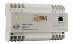
Gateway
| Power supply | |
| Mains voltage | 230 VAC +/- 10 % |
| Frequency | 45 up to 65 Hz |
| Power consumption | approx. 10 VA |
| Fuse protection | max. 2 A external required |
| Interfaces | |
| 1 Ethernet | RJ45, to connection on LAN Network Protocol: TCP/IP transmission: 10BaseT half duplex |
| 1 FRAKOStarkstrombus® | for connection to the FRAKO Energy Management System, according to EN 50170(P-Net) standardised fieldbus, RS 485 Transfer speed: 76.8 kbit/s |
| 1 Serial interface | 9 polige Sub-D-bush (female), RS 232 V.24, to device configuration Protocol: FRAKO internally high transmission rate: 115200 Baud, 8 Bit, 1 Stopbit,no equality |
| Display elements | 4 light-emitting diodes |
| Connections | screw terminals wire cross-section: max. 2.5 mm² |
| Mechanical construction | |
| Dimensions | 140x90x59 mm (WxHxD), DIN module case 8 TE |
| Ingress Protection | housing/terminals IP40/20 |
| Construction | Protection class II at VDE 0411 / DIN EN 61010-1 |
| Cases | flame-retardant UL94-V0 |
| Fitting | on standard rail 35 mm according to DIN EN 50022 |
| Mounting position | optional |
| Weight | approx. 0.5 kg |
| Operating Conditions | |
| Ambient temperature | 0 up to +50°C |
| Article-No. | 20-10210 |
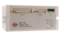
System Timer
| Power supply | |
| Mains voltage | 230 VAC +/-10 % |
| Frequency | 45 up to 65 Hz |
| Power consumption | approx. 5 VA |
| Fuse protection | max. 2 A external required |
| Interfaces | |
| Serial A | 25 pole Sub-D-bush (female), for connection of EM-DCF77 radio clock |
| Serial B | 9 pole Sub-D-bush (female), RS 232, for connection of a PC |
| FRAKO Starkstrombus® | For connection to the FRAKO Energy Management System, according to EN 50170(P-Net) standardized fieldbus, RS 485 High transmission rate: 76.8 kbit/s |
| Display elements | 3 light emitting diodes |
| Connections | in housing with screw terminals conductor cross-section: max. 2.5 mm² |
| Mechanical construction | |
| Dimensions | 158x75x120 mm (WxHxD) |
| Ingress protection | IP40 |
| Version | according to VDE 0411 protection class I (also DIN EN61010-1) |
| Material of case | PC with 10% GF, V-0 flame-adversely UL-94 V-0 |
| Installation | screw mounting or standard rail 35 mm according to DIN EN 50022 |
| Orientation | optional |
| Weight | approx. 0.8 kg |
| Operating conditions | |
| Ambient temperature | 0 up to +40°C |
| PC-requirements for the Softwarepackage EMT-SW | |
| Hardware | |
| Pentium min. 1 GHz clock frequency | |
| working memory min. 512 MB RAM | |
| free hard disk capacity 10 MB | |
| Ethernet 10/100 MB network connection or/and one free serial interface | |
| CD-ROM, SVGA-Graphic card | |
| colour screen with minimum resolution of 1024 x 768 | |
| Software | |
| Windows 2000 pro SP3 | |
| XP pro SP3 | |
| 2003 Server, IE5 | |
| Article-No. | 20-10300 |
Communications Processor

| Power supply | |
| Mains voltage | 230 VAC +/-10 % |
| Frequency | 50 to 60 Hz |
| Power consumption | max. 3 VA |
| Fuse protection | max. 2 A external required |
| Outputs | |
| serial interfaces A | 25 pole Sub-D-bush (female), RS 232, framework protocol 3964R, data protocol RK 512 |
| serial interfaces B | 9 pole Sub-D-bush (female), RS 232, for a connection of a PC |
| FRAKO Starkstrombus® | for connection to the FRAKO Energy Management System, according to EN 50170(P-Net) standardised fieldbus, RS 485 Transfer speed: 76.8 kbit/s |
| Display elements | 3 light emitting diode |
| Connections | in cases via connector strip |
| Mechanical construction | |
| Dimensions | 158x75x120 mm (WxHxD) |
| Ingress protection | IP50 |
| Version | Protection class I according to VDE 0411 / EN 61010 |
| Case | flame-adversely UL94-V0 (according to the manufacturer) |
| Installation | screw mounting or standard rail 35 mm according to DIN EN 50022 |
| Mounting position | optional |
| Weight | approx. 0.8 kg |
| Operating Conditions | |
| Ambient temperature | 0 up to +40°C |
| PC-Requirements for the Softwarepackage | |
| Hardware | |
| Pentium mind. 1 GHz clock frequency | |
| working memory min. 512 MB RAM | |
| free hard disk capacity10 MB | |
| Ethernet 10/100 MB network connection or/and one free serial interface | |
| CD-ROM | |
| SVGA-Graphic card | |
| colour screen with minimum resolution of 1024×768 | |
| Software | |
| Windows 2000 pro (min. SP3) | |
| Windows XP pro (min. SP1) | |
| Windows 2003 Server (min. SP1) | |
| Internet Explorer 5.5 | |
| Article-No. | 20-10202 |
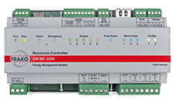
Optimization Controller
| Power supply | |
| Mains voltage | 100 V – 253 V AC or 100 V – 230 V DC |
| Frequency | 45 up to 65 Hz |
| Power consumption | 7 W / 18 VA |
| Inputs | |
| General | S0-Interfaces(DIN43864) for connection of potential free contacts Voltage with open contact: 15 V Max. Line resistance: 800 Ohm Short-circuit current: 18 mA Pulse frequency: 0.1 to 20 Hz |
| 3 Pulse Inputs | for power data acquisition from up to 3 meters with pulse outputs. Input 3 can also be used for acquiring reactive power data. |
| 1 Receiver | 1…1440 Minutes |
| 2 Profil Inputs | to the selection of 4 profiles |
| Outputs | |
| 5 Relaiskontakte(swichting channels) | bistable, 250V / 2A AC or 30V / 2A DC |
| 1 Relaycontact(distress throwing off channel) | bistable, 250V / 2A AC or 30V / 2A DC |
| 1 alarm contact | break contact 250V / 2A AC or 30V / 2 A DC |
| 1 Extension bus-interface | for connection up to 10 EMD1101 |
| 1 FRAKO Starkstrombus-Interface | for connection to FRAKO Energy Management System |
| Displaybus-Interface | for optional connection of max. 2 external Displays of Type EM-FD 2500 |
| Operating elements | Operation via external display EM-FD 2500 |
| Display elements | 15 LEDs |
| Connections | via plug-in terminals |
| conductor cross-section: max. 1.5 mm² | |
| Fuse Protection | max. 2A external required |
| Mechanical construction | |
| Dimensions | 296 x 260 x 133 mm (WxHxD) |
| Ingress Protection | IP30 (cases), IP10 (terminals) |
| Weight | approx. 0.4 kg |
| Protection class | Protection class II according to DIN/EN 61010 |
| Housing | flame-adversely UL 94-V0 |
| Installation | on standard rail 35 mm according to DIN EN 50022 |
| Operating Conditions | |
| Ambient temperature | 0°C up to +45°C |
| Storage temperature | -20°C up to +60°C |
| PC requirement for Device-Manager | |
| Hardware | |
| PC: CPU with min. 2 GHz, 1 Gbyte RAM, 200 Mbyte free hard disk capacity | |
| Software: | |
| Windows XP, SP 2 with installed.NET-Framework 3.5 Windows 7 (32 or 64 Bit) Windows 2008 Server R2 |
|
| Article-No. | 20-20071 |
Extension Module-Single Throw

| Power supply | |
| Mains voltage | 230 VAC -15 % up to +10 % |
| Frequency | 45…65 Hz |
| Power consumption | 4 VA |
| Fuse Protection | max. 2 A external required |
| Outputs | |
| 8 Switching Channels | normal open contact 250 VAC / 4 A |
| 1 Extension bus / FRAKO Starkstrombus® | 2-Wire-fieldbus, RS 485 |
| Operating elements | 8-fold DIP-switching series, 10-level rotary switch |
| Display elements | 9 light emitting diode |
| Connections | in cases via connector strip conductor cross-section: max. 2.5 mm² |
| Mechanical construction | |
| Dimensions | 158x75x120 mm (WxHxD) |
| Ingress Protection | IP40 |
| Version | Protection class 2 nach DIN/EN 61010 |
| Housing | flame-adversely UL94-V0 (according to the manufacturer) |
| Installation | screw mounting or standard rail 35 mm according to DIN EN 50022 |
| Mounting position | wall mounting, vertical |
| Weight | approx. 0.8 kg |
| Operating Conditions | |
| Ambient temperature | 0 up to +45°C |
| storage temperature | -20 up to +60°C |
| Article-No. | 20-21002 |
Mains Analysis Devices for Top-Hat Rail Mounting
| EM-PQ 2300 | EM-PQ 2200 | EM-PQ 2100 | EM-PQ 1500 M | ||||||||
| Voltage | 90-267 VAC or 100-360 VDC | 95-240 VAC; 135-340 VDC ± 10% | 95-240 VAC; 135-340 VDC ± 10% | removed from rated voltage | |||||||
| Frequency | 45…65 Hz | 45/65 Hz | 45/65 Hz | 50 Hz | |||||||
| Power consumption | max. 8 W | max. 9 VA | max. 9 VA | max. 7 VA | |||||||
| Contact termination 3/4/5-Conductor | ● / ● / ● | ● / ● / – | ● / ● / – | ● / ● / - | |||||||
| Current-Measurements Input | 5 x X/5A | 4 x X/1A, X/5A | 4 x X/1A, X/5A | 3 x X/5A (transformer current > 6 mA), galvanical isolated | |||||||
| Voltage-Measurements Input | 400/690 VAC (L-N/L-L) 3-phases 5-conductor system | 277/480 VAC (L-N/L-L) 3-phases 4-conductor system 480 VAC (L-L) 3-phases 3-conductor system | 277/480 VAC (L-N/L-L) 3-phases 4-conductor system 480 VAC (L-L) 3-phases 3-conductor system | 3 x 57-230 VAC ± 10% (external-/neutral conductor) 3 x 100-400 VAC ± 10% (external-/neutral conductor) | |||||||
| Harmonics V/A | 1-51 | 1-63 | 1-40 | – | |||||||
| Short Interruption | ● | ● | ● | – | |||||||
| Active Energy Class | 1 | 0,5 (…/5A); 1 (…/1A) | 0,5 (…/5A); 1 (…/1A) | 1 | |||||||
| Analoge In-/Outputs | – / 2 (0-10 V or 0-20 mA or 4-20 mA) | 1 temperature / – | 1 temperature / – | – / 1 (max. 30 VDC, 100 mA), (4-20 mADC passiv) | |||||||
| Digitale In-/Output | 4 / 2 | 2 / 2 | 2 / 2 | – / 1 (max. 48 VDC, 100 mA); 1 (max. 30 VDC, 100 mA) | |||||||
| Memory Min-/Maxvalue | ● | ● | ● | ● | |||||||
| Memory size | 256 MB | 128 MB | 128 MB | – | |||||||
| Interfaces | |||||||||||
| Ethernet | ● | ● | ● | – | |||||||
| FRAKO Energy Management System | ● via FRAKO Starkstrombus®Intranet (Ethernet)Modbus/TCP | ● Connection via- Modbus RTU (RS 485) or – Modbus/TCP (Ethernet) | ● Connection via- Modbus RTU (RS 485) or – Modbus/TCP (Ethernet) | ● via FRAKO Starkstrombus® | |||||||
| RS 232 / RS 485 | – / ● | ● / ● | ● / ● | – / – | |||||||
| Profibus DP | – | ● | – / – | ||||||||
| Webserver / Email | – / ● | ● / ● | ● / ● | – / – | |||||||
Mains Analysis Devices
| EM-PQ 3000 | EM-PQ 2500 | EMA 1101 | EMA 1296 | ||||||||
| Voltage | 95-240 VAC; 80-340 VDC ± 10% | 95-240 VAC; 80-340 VDC ± 10% | 230 VAC ± 10% | 110-440 VAC oder 120-350 VDC ± 20% | |||||||
| Frequency | 45/65 Hz | 45/65 Hz | 48…62 Hz | 50/60 Hz ± 10% | |||||||
| Power consumption | max. 9 VA | max. 9 VA | max. 7VA | max. 5VA | |||||||
| Contact termination 3/4/5-conductor | ● / ● / – | ● / ● / – | ● / ● / – | ● / ● / -; 2-conductor and single-phase | |||||||
| Current-Measurements | 4 x X/1A, X/5A | 4 x X/1A, X/5A | 3 x X/5A (Wandlerstrom > 6 mA), galvan. getrennt | 3 x X/5A (X adjustable of 5-9999 A); 3 x 50-500 VAC (external-/external conductor), Overload 800 VAC; | |||||||
| Voltage-Measurements | 417/720 VAC (L-N/L-L) 3-phases 4-conductor systems 480 VAC (L-L) 3-phases 3-conductor systems | 417/720 VAC (L-N/L-L) 3-phases 4-conductor systems 480 VAC (L-L) 3-phases 3-conductor systems | 3 x 250-550 VAC (external-/external conductor) 1);3 x 50-105 VAC (external-/external conductor) 2) | 3 x 28-289 VAC (external-/neutral conductor), Overload 800 VAC | |||||||
| Harmonics V/A | 1-63 | 1-40 | 1-19 | – | |||||||
| Short Interruption | ● | ● | – | – | |||||||
| Active Energy Class | 0.2 (…/5A) | 0.2 (…/5A) | 2 | 2 | |||||||
| Analoge In-/Outputs | – / – | – / – | 2 temperature inputs3) / – | – / – | |||||||
| Digitale In-/Outputs | 8 / 5 | 8 / 5 | Collective input for selection of 2 profiles/ 1 alarm signalling contact 250 VDC, max. 3 A | – / optional Plug-In Module for active- and reactive working | |||||||
| Memory Min-/Maxvalue | ● | ● | ● | ● | |||||||
| Memory size | 256 MB | 256 MB | – | – | |||||||
| Interfaces | |||||||||||
| Ethernet | ● | ● | – | – | |||||||
| FRAKO Energie-Management-System | ● Connection via- Modbus RTU (RS 485) or – Modbus/TCP (Ethernet) | ● Connection via- Modbus RTU (RS 485) or – Modbus/TCP (Ethernet) | ● via FRAKO Starkstrombus® | ● optional Plug-In module enable the connection via Modbus RTU | |||||||
| RS 232 / RS 485 | – / ● | – / ● | ● (optional at EMA 1101, EMA 1101 105 V) / – | – / – | |||||||
| Profibus DP | ● | ● | ● (only -DP – Variantes) | – | |||||||
| Webserver / Email | – / – | ● / ● | – / – | – / – | |||||||
Display Unit
| EM-FD 2500 | EM-FD 1500 | ||||||||||
| Voltage | über EM-Gerät versorgt | 24 VDC ± 15% or 85-264 VAC | |||||||||
| Frequency | – | 50/60 Hz | |||||||||
| Power consumption | max. 3 VA | max 3 VA | |||||||||
| Operating-/Displayelement | 9 Buttons / bright LC-Display / 1 LED | 9 Button / bright LC-Display | |||||||||
| Interfaces | |||||||||||
| CAN-Bus | ● | ||||||||||
| RS 232 / RS 485 | – | – | |||||||||
Power Factor Control Relay with Bus Interface

| Power supply | |||||||||||
| Mains voltage | 230/400 VAC -15 % up to +15% | ||||||||||
| Frequency | 48 up to 62 Hz | ||||||||||
| Power consumption | 9 VA at 0 resp. 13 VA at 12 switching control contacts | ||||||||||
| Fuse Protection | max. 4 A external required | ||||||||||
| Measurements Inputs | |||||||||||
| Voltage circuit: | 100 VAC to 690 VAC +/- 10 %, Power consumption: 0.5 VA | ||||||||||
| Voltage circuit | for current transformer X/1 A bis X/5 A (min. transformer current > 20 mA), Power consumption: max. 1.8 VA at 5 A transformer-rated current | ||||||||||
| Outputs | |||||||||||
| 12 control contacts: | Relay contacts, potential-free, | ||||||||||
| switching voltage: 380 VAC according to VDE0110 group B, 250 VAC according to VDE0110 group C, | |||||||||||
| total switching current: 2 x 5 A, | |||||||||||
| switching capacity: 1800 VA | |||||||||||
| 1 alarm signalling contact: | 250 VAC/ 4 A, potential-free, closed on alarm | ||||||||||
| Inputs | |||||||||||
| 1 tariff input | choice of 2 separate control programs (z.B. HT/NT) | ||||||||||
| Interfaces (Mode of operation optionally) | |||||||||||
| 1 FRAKOStarkstrombus® | for connection to FRAKO Energy Management System, according to EN 50170(P-Net) standardised fieldbus, RS 485 transfer speed: 76.8 kbit/s |
||||||||||
| 1 RS 232-Interface | via RS232-Adapter (Option) direct connection to the PC transfer speed: 19200 Baud |
||||||||||
| Undervoltage control | bei Netzunterbrechung im Spannungspfad > 15ms werden zugeschaltete Kondensatorstufen abgeschaltet, bei Wiederkehr werden benötigte Stufen zugeschaltet | ||||||||||
| Operating elements | membrane keyboard with 4 buttons | ||||||||||
| Display elements | 18 light emitting diodes, 4 1/2-digit numeric display | ||||||||||
| Connections | via connector strips (included with delivery) | ||||||||||
| Mechanical construction | |||||||||||
| Dimensions | front panel dimension: 144×144 mm (DIN 43700) switch panel aperture: 138×138 mm (DIN 43700) installation depth: 105 mm |
||||||||||
| Ingress Protection | cases/terminals IP53/20 (when using the sealing ring as an accessory) | ||||||||||
| Version | Protection class II according to VDE 0160, Isolation groupe B (when using the insulated fastening screws as accessories) | ||||||||||
| Housing | flame-adversely UL94-V0 | ||||||||||
| Installation | From the front panel using a screwdriver | ||||||||||
| Mounting position | optional | ||||||||||
| Weight | approx. 1.2 kg | ||||||||||
| Operating Conditions | |||||||||||
| Ambient temperature | -25°C bis +60°C according to DIN VDE 0660, Part 500 paragraph.6.1.1.1 | ||||||||||
| Article-No. | 20-50006 | ||||||||||
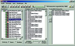
Visualization Software
| PC-requirements for small and medium systems: | |||||||||||
| Hardware | |||||||||||
| min. 3 GHz Processor Dual-Core | |||||||||||
| 4 GB working memory | |||||||||||
| 1 GB free hard disk memory | |||||||||||
| Software | |||||||||||
| Windows 7 (x32/x64) | |||||||||||
| Windows Server (2003 R2/2008 R2) | |||||||||||
| Windows DOT NET 4.0 SP1 | |||||||||||
| * registered trademarks of Microsoft Coorporation | |||||||||||
| FRAKO-NET V1.24.0000 (or newer) | |||||||||||
| SQL database Firebird 2.0 (included in FRAKO-NET) | |||||||||||
| Article-No. | 20-10649 | ||||||||||
Cost Center Handling Software
| PC-requirements: | |||||||||||
| Hardware | |||||||||||
| Pentium, mind. 2 GHz clock frequency | |||||||||||
| min. 1 GB working memory | |||||||||||
| 6 GB free hard disk memory | |||||||||||
| Ethernet 10/100 MB network connection or/and one free serial interface | |||||||||||
| CD-ROM-drive | |||||||||||
| SVGA-graphic card | |||||||||||
| Colour screen, minimum resolution: 1024 x 768 Pixel | |||||||||||
| Software | |||||||||||
| Database FRAKO-NET DB or FRAKO EMIS-DB | |||||||||||
| Windows 2000 pro (min. SP3) | |||||||||||
| Windows XP pro (min. SP1) | |||||||||||
| Windows 2003 Server (min. SP1) | |||||||||||
| Internet Explorer 5.5 | |||||||||||
| Excel (from Version 2000) | |||||||||||
| * registered trademarks of Microsoft Coorporation | |||||||||||
| Article-No. | 20-10488 | ||||||||||
EMG-OPC-Server
| PC-requirements for small and medium systems: | |||||||||||
| Hardware | |||||||||||
| Pentium, mind. 1 GHz clock frequency | |||||||||||
| min. 512 MB working memory | |||||||||||
| 10 MB free hard disk memory | |||||||||||
| Ethernet 10/100 MB network connection or/and one free serial interface | |||||||||||
| CD-ROM drive | |||||||||||
| SVGA-graphic card | |||||||||||
| colour screen with minimum resolution of 1024 x 768 | |||||||||||
| Software | |||||||||||
| Windows 2000 pro (min. SP3) | |||||||||||
| Windows XP pro (min. SP1) | |||||||||||
| Windows 2003 Server (min. SP1) | |||||||||||
| Internet Explorer 5.5 | |||||||||||
| SQL database Firebird 2.0 (included in FRAKO-NET) | |||||||||||
| Article-No. | 20-10649 | ||||||||||